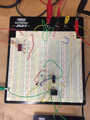
- Digital
- Motor
- Relay
- Opamp
- Temperature sensor
- LED
The setup should be considered to last 30 seconds.
Video 1: Rube Goldberg Explained
Video 2: Rube Goldberg in action
Make sure to include enough photos, videos, and explanations for each “transition” or step. Explain your circuits.
- Clearly in our circuit the relay was giving us a hard time. Other than that the circuit pretty much functioned according to plan. We showed the increasing voltage that was coming from the op-amp and into the relay to help viewers understand the circuit better. When the mechanism fell over, the slight bounce is just enough to release pressure on the switch. This is why there are random weight blocks on the back side and ultimately why I ended up pressing on the mechanism in the video.
Make sure to include enough photos, videos, and explanations for each “transition” or step. Explain your circuits.
 |
| Photo 1: Shows the motor attached to the falling mechanism that will trigger the 7 segment display to turn on |
 |
| Photo 2: Overview of the 7 segment display, op-amp, and relay |
 |
| Photo 3: Shows 555 timer |
 |
| Photo 4: A closer view of the heat sensor, op-amp, and relay |
 |
| Photo 5: Showing the connections made in order to produce the number 3 on the 7 segment display |
The following pictures are schematics of our Rube Goldberg's components layout
 |
| Schematic 1: Is a block diagram of our Rube Goldberg circuit |
 |
| Schematic 2: Is part one of our Rube Goldberg Circuit |
 |
| Schematic 3: Is part two of our Rube Goldberg Circuit |
- Problem 1: One problem that we encountered during this Rube Goldberg build was getting the gain on the op-amp to be just right. Instead of using two resistors, we ended up having to use three because we couldn't find one resistor to be precise enough. I am forgetful of the two values that we put in series to make this happen, but it worked nonetheless.
- Problem 2: Another problem that we faced during this build was getting everything to work correctly at the end of it. As you can see in the video, the falling mechanism we built did not have enough weight to trigger the switch on the bottom side. This is why you can see me push down on it to light up our group number. The motor was also very weak and we had little supplies available to attach to it.
I like how you guys added the circuit schematic in your blog. I also like how you separated the explain and demonstration into 2 videos. I know from previous labs that getting everything to work is hard and then having to go back and see where the problem and hopefully finding it or having to start over, because you can't.
ReplyDelete