
1. You will use the OPAMP in “open-loop” configuration in this part, where input signals will be applied directly to the pins 2 and 3.
 |
Table 1: Non-Inverting
Op-amp
|
 |
| Figure 1: Plot of Vin vs. Vout for an Non-Inverting Op-amp |
- Since it is an inverting op-amp, if the provided voltage going into Vin is positive, the output Vout would be negative because the voltage at terminal (-) is greater than voltage at terminal (+). Similarly Vout would be positive if the V(-) terminal was less than the voltage at the V(+) terminal.
- The Ideal results for out plot for this would be the output of [-5, 5]V instead of our [-3.73, 4.5]V range.
b.) Apply 0V to the non-inverting input. Sweep the inverting input (Vin) from -5V to 5V with 1V steps. Take more steps around 0 V (both positive and negative). Create a table for Vin and Vout. Plot the data (Vout vs Vin). Discuss your results. What would be the ideal plot?
 |
| Table 2: Inverting Op-Amp |
 |
| Figure 2: Plot of Vin vs. Vout for an Inverting Op-amp |
- The Op-Amp's output will be equal to the V+ input if the Non-Inverting (+) input is greater than the Inverting Input (-).
- An Ideal Model for an Non-Inverting Op-amp circuit would see an output of +5V for any positive input, an output of 0 for a 0V input, and -5V for any Negative input.
Calculated Data
 |
Table 1: Calculated data
for Non-Inverting op-amp
|
 |
| Figure 1: Plotted calculated data for Non-Inverting op-amp |
Measured Data
 |
| Table 2: Measured data for Non-Inverting op-amp |
 |
| Figure 2: Plotted measured data for Non-inverting op-amp |
- The calculated gain for this Non-Inverting amplifier should have followed (1+R2/R1). We calculated that our constructed Non-Inverting amplifier would theoretically have a gain of about 3x the amount of voltage, surprisingly our measured Vout values exceeded our calculated ones for our (+1V and -1V) Vin inputs.
3. Create an inverting amplifier. (Rf = 2 kΩ, Rin = 1 kΩ). Sweep Vin from -5V to 5V with 1V steps. Create a table for Vin and Vout. Plot the measured and calculated data together.
Calculated Data
 |
Table 3: Calculated data
for Inverting Op-amp
|
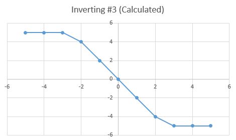 |
| Figure 3: Plotted calculated data for Inverting Op-amp |
Measured Data
 |
| Table 4: Measured data for Inverting Op-amp |
 |
| Figure 4: Plotted measured data for Inverting Op-amp |
- The calculated gain for this Inverting amplifier should have followed 1*(R2/R1). We calculated that our constructed Inverting amplifier would theoretically have a gain of about -2x the amount of voltage, surprisingly our measured Vout values once again exceeded our calculated ones but this time only for our (-1V, -2V) Vin inputs.
- The open loop configuration of the Op-amp does not actually act as an amplifier, but instead acts as a comparator. By definition a comparator: is a device for comparing a measurable property or thing with a reference or standard. If the positive(+) Non-Inverting input exceeds the negative(-) Inverting input, it's output is equal to whatever voltage is present on the V+ input. Conversely if the negative(-) Inverting input exceeds the positive(+) Non-Inverting input it's output is equal to whatever voltage is present on the V- input.
- However, if you connect a pair of resistors to the op-amp then it can act as an amplifier. There are two types of amplifier configurations (Inverting and Non-Inverting) the Inverting Amplifier has a gain of -1*(R2/R1), as for the Non-Inverting amplifier its gain will be 1+(R2/R1).
Temperature Sensor:
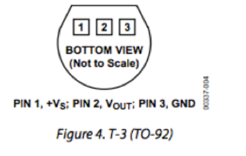
Put TMP36 temp sensor on breadboard. Connect the +VS to 5V and GND to ground.
- We attached fixed 5V to the TMP36 temperature sensor, and recorded the following data, displayed on (Table 1) below.
 |
| Table 1: Temperature sensor voltage output, tested at various heats. |
- Instead of just using the palms of our hands, we wanted to test various types of temperatures on the sensor, so we decided to make a data table for the different Vout outputs. There was no known discrete controls for the heat guns heat-output, plus temperatures can differ depending on the range its from the component. So we estimated that the temperature given off by the heat gun onto the board/sensor would be around 90℃ because the board was pretty warm but still touchable by the hand.
Relay:
1. Connect your DC power supply to pin 2 and ground pin 5. Set your power supply to 0V. Switch your multimeter to measure the resistance mode; use your multimeter to measure the resistance between pin 4 and pin 1. Do the same measurement between pin 3 and pin 1. Explain your findings (EXPLAIN).
2. Now sweep your DC power supply from 0V to 8V and back to 0V. What do you observe at the multi-meter (resistance measurements similar to #1)? Did you hear a clicking sound? How many times? What is the “threshold voltage values” that cause the “switching?” (EXPLAIN with a VIDEO).
3. How does the relay work? Apply a separate DC voltage of 5V to pin 1. Check the voltage value of pin 3 and pin 4 (each with respect to ground) while switching the relay (EXPLAIN with a VIDEO).
1. Connect positive end of the LED diode to the pin 3 of the relay and negative end to a 100Ω resistor. Ground the other end of the resistor. Negative end of the diode will be the shorter wire.
2. Apply 3V to pin 1.
3. Turn LED on/off by switching the relay. Explain your results in the video. Draw the circuit schematic (VIDEO)
2. Use your temperature sensor as your input. Do you think you can generate enough voltage to trigger the relay? (EXPLAIN)
3. Design a system where LED light turns on when you heat up the temperature sensor. (CIRCUIT schematic and explanation in a VIDEO)
4. BONUS! Show the operation of the entire circuit. (VIDEO)
- With a power supply is set to 0 V there is no resistance across pins (1 & 4), because the contacts across the relay remain open unless a certain amount of required voltage is provided. However, there is a measurable resistance across pins (1 & 3), of 1.5Ω, this is because voltages applied within the range of 0-5V are allowed to pass through the contacts.
2. Now sweep your DC power supply from 0V to 8V and back to 0V. What do you observe at the multi-meter (resistance measurements similar to #1)? Did you hear a clicking sound? How many times? What is the “threshold voltage values” that cause the “switching?” (EXPLAIN with a VIDEO).
Testing Voltage ranges on a relay.
- *Note that our relay was broken for all the videos containing it, we did our best to explain what would happen.*
- We didn't hear any clicking sounds, but we imagine it would a properly working 12V relay would have clicked twice.
- The threshold values are: [Min: 4.2V, Max: 6.3V]
3. How does the relay work? Apply a separate DC voltage of 5V to pin 1. Check the voltage value of pin 3 and pin 4 (each with respect to ground) while switching the relay (EXPLAIN with a VIDEO).
Explains how a relay works, with respect to ground.
- *Note that our relay was broken for all the videos containing it, we did our best to explain what would happen.*
- The clicking sound is the switch being triggered by pin 1's voltage surpassing the required amount, causing the switch to allow voltage to flow from pin 2 to pin 4, the 2nd click is the switch switching back to pin 3 because the minimum voltage is not being supplied to pin 1.
LED + Relay:
2. Apply 3V to pin 1.
3. Turn LED on/off by switching the relay. Explain your results in the video. Draw the circuit schematic (VIDEO)
 |
| Photo: Schematic of the Relay has been triggered on and switched to supply 3V to the LED in the circuit. |
Turning LED on/off using a relay.
- *Note that our relay was broken for all the videos containing it, we did our best to explain what would happen.*
- The relay would eventually switch around 5-6 volts, however it did not, so we just showed how the relay would work on pin 3.
Operational Amplifier (data sheet under Bb/week 6)
1. Connect the power supplies to the op-amp (+10V and 0V). Show the operation of LM124 operational amplifier in DC mode with a non-inverting amplifier configuration. Choose any Op-Amp in the IC. Method: Use several R1 and R2 configurations and change your input voltage (voltages between 0 and 10V) and record your output voltage. (EXPLAIN with a TABLE) |
| Data Table: Non-Inverting Op-amp with different variables. |
- In the data table above we decided to help best explain the gain, we would take into account the gain equation and show many of the different kinds. We used smaller R2 resistors than our R1 resistors. The data shows where the voltage threshold for Vout is.
2. Use your temperature sensor as your input. Do you think you can generate enough voltage to trigger the relay? (EXPLAIN)
- Yes, we believe we can generate enough voltage from the amplifier to get the relay to switch pins. We calculated the gain using the non-inverting op-amp equation, to best reach the our relays trigger voltage of about 6.4V. To do this we had to figure out which R2 and R1 configuration would get us as close as possible to our desired value.
3. Design a system where LED light turns on when you heat up the temperature sensor. (CIRCUIT schematic and explanation in a VIDEO)
 |
| A drawing of our circuit |
Video explaining what is going on in our circuit, based off of our drawing above.
4. BONUS! Show the operation of the entire circuit. (VIDEO)
Bonus video: Showing circuit operation
- *Note that almost every component that we originally got for this lab was broken or didn't work the way it should have.*